

How To Center Camera In Blender
A camera is an object that provides a means of rendering images from Blender. Information technology defines which portion of a scene is visible in the rendered image.
Cameras are invisible in renders, and then they practise not have whatsoever material or texture settings. However, they do have Object and Editing setting panels available which are displayed when a camera is the active object.
Properties
Reference
- Mode
-
Object Mode
- Editor
Lens
Blazon
The camera lens options command the way 3D objects are represented in a 2D prototype.
- Perspective
-
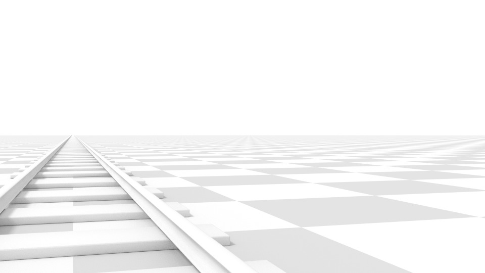
This matches how you view things in the real globe. Objects in the distance will appear smaller than objects in the foreground, and parallel lines (such every bit the runway on a railroad) will appear to converge as they get farther abroad.
- Focal Length/Field of View
-
The Focal Length controls the corporeality of zoom, i.e. the amount of the scene which is visible all at once. Longer focal lengths result in a smaller FOV (more zoom), while short focal lengths allow yous to run into more of the scene at one time (larger FOV, less zoom).
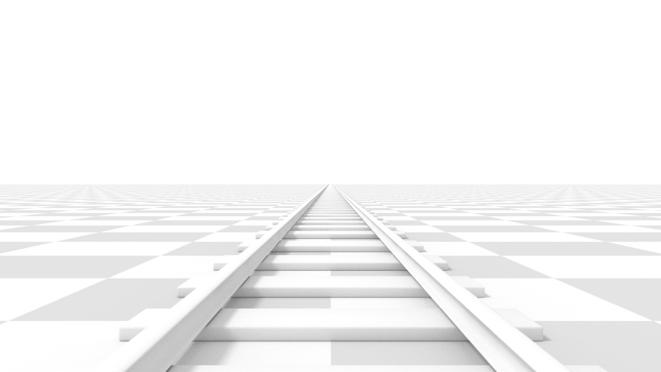
Perspective camera with 35 mm focal length.
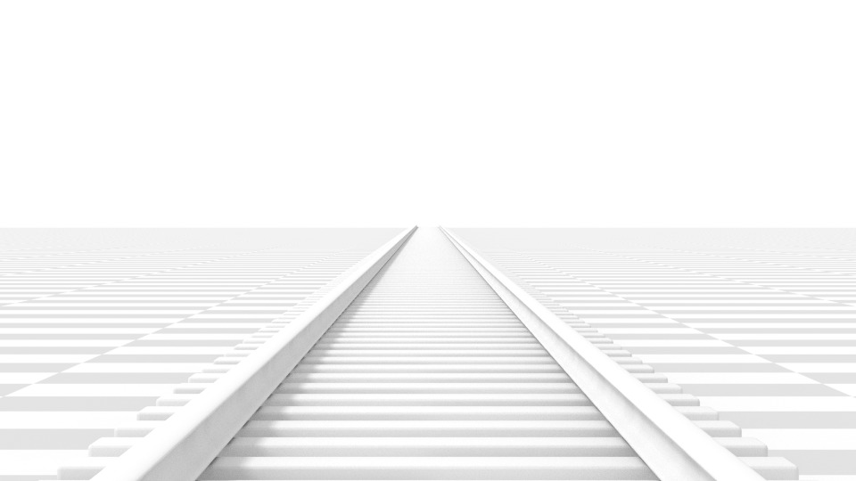
Perspective camera with 210 mm focal length instead of 35 mm.
- Lens Unit
-
The focal length tin can exist set either in terms of millimeters or the actual Field of View every bit an angle.

Hint
While the photographic camera is moving towards an object the Focal Length belongings tin can exist decreased to produce a Dolly Zoom camera effect, or vice versa.
This video demonstrates the Dolly Zoom photographic camera effect.
- Orthographic
-
With Orthographic perspective objects always appear at their actual size, regardless of distance. This ways that parallel lines appear parallel, and practice not converge like they do with Perspective.
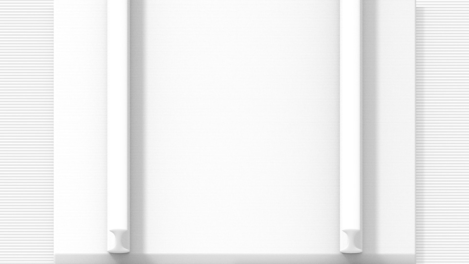
Render from the same photographic camera bending as the previous examples, only with orthographic perspective.
- Orthographic Calibration
-
This controls the credible size of objects projected on the image.
Note that this is effectively the but setting which applies to orthographic perspective. Since parallel lines do non converge in orthographic way (no vanishing points), the lens shift settings are equivalent to translating the camera in the 3D Viewport.

- Panoramic
-
Panoramic cameras only work in Cycles. Run across the Cycles panoramic camera settings for more data.
- Shift
-
Allows for the aligning of vanishing points. Vanishing points refer to the positions to which parallel lines converge. In these render examples, the most obvious vanishing point is at the terminate of the railroad.
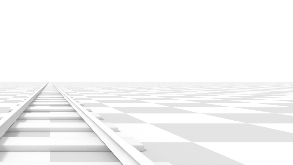
Horizontal lens shift of 0.330.
Rotation of the camera object instead of a lens shift.
Observe how the horizontal lines remain perfectly horizontal when using the lens shift, but exercise go skewed when rotating the photographic camera object.
Annotation
Using lens shift is equivalent to rendering an prototype with a larger FOV and cropping it off-center.
- Clip Starting time and Stop
-
The interval in which objects are directly visible. Any objects outside this range nevertheless influence the prototype indirectly, as further light bounces are not clipped.
Note
For viewport rendering, setting clipping distances to limited values is important to ensure sufficient rasterization precision. Ray tracing renders do not suffer from this issue so much, and as such more extreme values can safely be set.
Tip
When Limits in the Viewport Brandish panel is enabled, the prune bounds will be visible as 2 yellow connected dots on the photographic camera's line of sight.
Depth of Field
Real-world cameras transmit calorie-free through a lens that bends and focuses it onto the sensor. Because of this, objects that are a certain distance away are in focus, just objects in front and behind that are blurred.
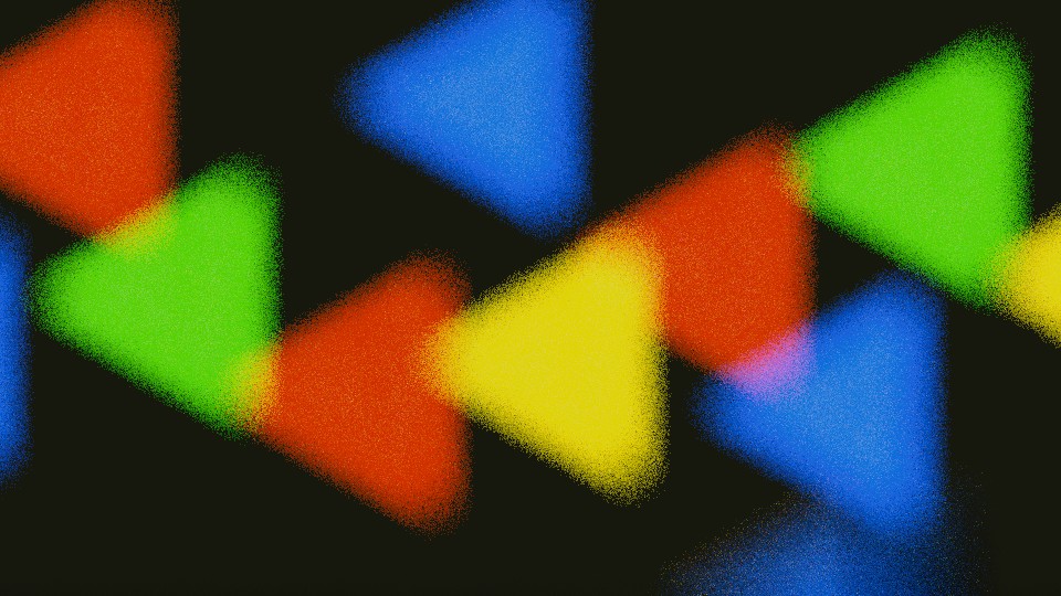
Example of DOF bokeh result.
The surface area in focus is chosen the focal point and can be set using either an verbal value, or by using the distance between the camera and a chosen object:
- Focus Object
-
Choose an object which will determine the focal signal. Linking an object volition deactivate the distance parameter.
- Focal Distance
-
Sets the altitude to the focal point when no Focus Object is specified. If Limits are enabled, a xanthous cross is shown on the camera line of sight at this altitude.
Hint
Hover the mouse over the Distance property and press East to use a special Depth Picker. So click on a point in the 3D Viewport to sample the altitude from that point to the camera.
Discontinuity
- F-Terminate
-
F-Cease ratio that defines the corporeality of blurring. Lower values requite a strong depth of field effect.
- Blades
-
Full number of polygonal blades used to alter the shape of the blurred objects in the render, and render preview. As with the viewport, the minimum amount of blades to enable the bokeh effect is 3, resulting in a triangular-shaped mistiness.
- Rotation
-
Rotate the polygonal blades along the facing axis, and volition rotate in a clockwise, and counter-clockwise fashion.
- Ratio
-
Change the corporeality of distortion to simulate the anamorphic bokeh result. A setting of one.0 shows no distortion, where a number below 1.0 will crusade a horizontal baloney, and a college number will cause a vertical baloney.
Camera
These settings adjusts properties that relate to a physical photographic camera body. Several Presets tin be chosen to match real-world cameras.
- Sensor Fit
-
Adjusts how the camera'due south sensor fits within the outputs dimension adjusting the angular field of view.
- Auto
-
Calculates a foursquare sensor size based on the larger of the Resolution dimensions.
- Horizontal
-
Manually adjust the Width of the sensor, the Height is calculated based on the aspect ratio of the output's Resolution.
- Vertical
-
Manually adjust the Height of the sensor, the Width is calculated based on the aspect ratio of the output's Resolution.
- Size / Width, Height
-
This setting is an alternative way to control the field of view, as opposed to modifying the focal length. It is useful to match a photographic camera in Blender to a physical camera and lens combination, e.g. for motility tracking.
Prophylactic Areas
Safe areas are guides used to position elements to ensure that the most of import parts of the content can be seen across all screens.
Dissimilar screens have varying amounts of Overscan (specially older Telly sets). That means that not all content will be visible to all viewers, since parts of the image surrounding the edges are not shown. To work effectually this trouble Television set producers defined two areas where content is guaranteed to be shown: action safe and title safe.
Modern LCD/plasma screens with purely digital signals have no Overscan, yet safe areas are nonetheless considered all-time exercise and may be legally required for broadcast.
In Blender, safe areas tin can be prepare from the Photographic camera and Sequencer views.
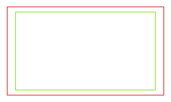
Carmine line: Activeness rubber. Light-green line: Title rubber.
The Safety Areas tin be customized by their outer margin, which is a percentage scale of the area between the eye and the render size. Values are shared betwixt the Video Sequence editor and photographic camera view.
- Championship Safe Margins 10/Y
-
Also known every bit Graphics Condom. Place all of import information (graphics or text) within this area to ensure it tin can be seen by the majority of viewers.
- Activeness Condom Margins X/Y
-
Brand sure any significant action or characters in the shot are inside this area. This zone also doubles as a sort of "margin" for the screen which can exist used to continue elements from piling upward against the edges.
Tip
Each country sets a legal standard for broadcasting. These include, amongst other things, specific values for safe areas. Blender defaults for safe areas follow the EBU (European Union) standard. Make sure you lot are using the correct values when working for circulate to avoid any trouble.
Center-Cut Rubber Areas
Center-cuts are a second fix of safe areas to ensure content is seen correctly on screens with a different aspect ratio. Former TV sets receiving 16:9 or 21:nine video will cut off the sides. Position content within the heart-cut areas to make sure the most important elements of your composition tin nevertheless exist visible in these screens.
Blender defaults evidence a 4:three (square) ratio within 16:9 (widescreen).
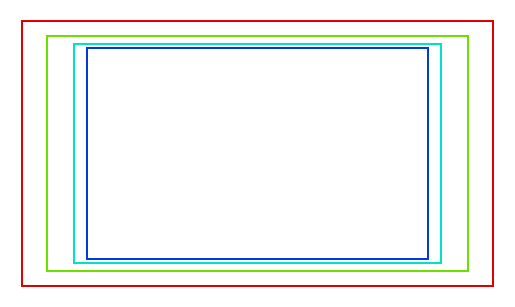
Cyan line: action centre safe. Blue line: title center safe.
Background Images
A groundwork flick in your camera can exist very helpful in many situations: modeling is obviously one, only it is too useful when painting (e.g. y'all can take reference pictures of faces when painting textures direct on your model…), or animation (when using a video equally background), etc.
- Groundwork Source
-
The source of the background image.
- Image
-
Use an external paradigm, paradigm sequence, video file or generated texture.
- Movie Prune
-
Employ ane of the Movie Clip data-blocks.
- Active Clip
-
Display a Movie Clip from the scene'due south Agile Clip.
- Render Undistorted
-
Brandish the background prototype using undistorted proxies when available.
- Proxy Render Size
-
Select between total (non-proxy) display or a proxy size to draw the background image.
- Color Space
-
The color infinite the image or video file uses within Blender.
- Opacity
-
Controls the transparency of the background epitome.
- Depth
-
Choose whether the image is shown behind all objects, or in front of everything.
- Frame Method
-
Controls how the image is placed in the camera view.
- Stretch
-
Forces the image dimensions to friction match the photographic camera bounds (may alter the aspect ratio).
- Fit
-
Scales the image down to fit inside the camera view without altering the aspect ratio.
- Crop
-
Scales the image up so that it fills the entire camera view, simply without altering the aspect ratio (some of the image will be cropped).
- Beginning 10, Y
-
Positions the groundwork image using these offsets.
In orthographic views, this is measured in the normal scene units. In the camera view, this is measured relative to the photographic camera premises (0.one volition start it by 10% of the view width/acme).
- Rotation
-
Rotates the image around its center.
- Scale
-
Scales the prototype up or down from its heart.
- Flip
-
- Ten
-
Swaps the image around, such that the left side is now on the correct, and the correct at present on the left.
- Y
-
Swaps the image around, such that the tiptop side is at present on the bottom, and the lesser now on the elevation.
Viewport Display
Camera view displaying safe areas, sensor and proper noun.
- Size
-
Size of the camera visualization in the 3D Viewport. This setting has no effect on the render output of a camera. The camera visualization tin also be scaled using the standard Scale S transform key.
- Evidence
-
- Limits
-
Shows a line which indicates Start and End Clipping values.
- Mist
-
Toggles viewing of the mist limits on and off. The limits are shown every bit 2 connected white dots on the camera line of sight. The mist limits and other options are fix in the World console, in the Mist section.
- Sensor
-
Displays a dotted frame in camera view.
- Name
-
Toggle name display on and off in photographic camera view.
Limerick Guides
Composition Guides enable overlays onto the camera display that can assist when framing a shot.
- Thirds
-
Adds lines dividing the frame in thirds vertically and horizontally.
- Heart
-
- Heart
-
Adds lines dividing the frame in half vertically and horizontally.
- Diagonal
-
Adds lines connecting opposite corners.
- Golden
-
- Ratio
-
Divides the width and superlative into Gold proportions (well-nigh 0.618 of the size from all sides of the frame).
- Triangle A
-
Displays a diagonal line from the lower left to upper correct corners, and so adds perpendicular lines that laissez passer through the acme left and bottom right corners.
- Triangle B
-
Same equally A, but with the contrary corners.
- Harmony
-
- Triangle A
-
Displays a diagonal line from the lower left to upper right corners, then lines from the tiptop left and lesser correct corners to 0.618 the lengths of the reverse side.
- Triangle B
-
Same as A, just with the opposite corners.
- Passepartout
-
This option darkens the area outside of the camera's field of view. The opacity of the passepartout can be adapted using the value slider.

Source: https://docs.blender.org/manual/en/latest/render/cameras.html
Posted by: vasquezsomforeatty.blogspot.com
0 Response to "How To Center Camera In Blender"
Post a Comment